In the last G-Engine post, we got the game loop and frame “delta time” calculations working. We’ve now got a blank, empty game window - yay? Despite the unimpressive result, we’ve got a beating heart under the hood: an update loop being called at roughly 60 frames per second.
Empty windows are no fun, so my next goal is to get something - anything - rendering in the game window. Graphics are a vital and exciting part of any game, and rendering can give us vital visual feedback as we move on to implementing and debugging 3D object placement, cameras, rotations, and data loading for 3D meshes and animations.
This post will focus on rendering a single triangle on screen. Though the result is simple, we’ll cover a lot of ground towards building a 3D rendering system that will be extended and enhanced as we move forward.
What is Rendering?
Rendering or drawing is the act of filling the contents of your computer screen with colors to create images. By displaying many static images in quick succession, we can give the impression of vibrant, animated, living 3D worlds.
We use a 2D array of color data, called a color buffer, to tell the computer screen what colors to display. Applications write to the color buffer, and the monitor displays the contents of the color buffer. Each element in the color buffer is called a pixel, and each pixel in the color buffer is made up of red, green, and blue values.
Games usually render once per frame. But it is also possible (and fairly common) to simulate multiple frames and only render the last one. We won’t discuss that here, though.
A renderer is the part of a game or other software that is responsible for rendering every object to screen. Generally, a renderer will iterate over a list of “renderable” objects and render each one in turn. Rendering occurs by sending “draw commands” to an underlying graphics library, such as OpenGL or DirectX.
The renderer must tackle several challenges. It may need to deal with rendering both opaque and translucent/transparent objects. Determining the correct order to render multiple objects is also more complicated than it may seem. Performing rendering calculations quickly enough to maintain a 30FPS or even 60FPS frame rate can also be tricky.
A “2D renderer” focuses only on rendering 2D objects, like image files (sometimes called textures). 2D rendering is relatively simple: we just copy a rectangular region of colors from a texture to a desired rectangular region of the color buffer. Since both the texture and the color buffer consist of pixels, it’s simply a matter of copying the pixel data from the source to the destination.
Rendering in 3D
A “3D renderer” renders 3D objects, which may also be referred to at various times as models, meshes, 3D geometry, or 3D shapes. The building block for 3D objects is a vertex. A vertex can have several attributes, such as position, color, or texture coordinates. For our current needs, position is most important. In 3D space, a vertex’s position is defined using a 3D cartesian coordinate (x, y, z).
To render anything meaningful, a 3D object usually needs at least three vertices, which make a single triangle. You can think of a 3D object as a collection of triangles, where each triangle consists of three vertices.
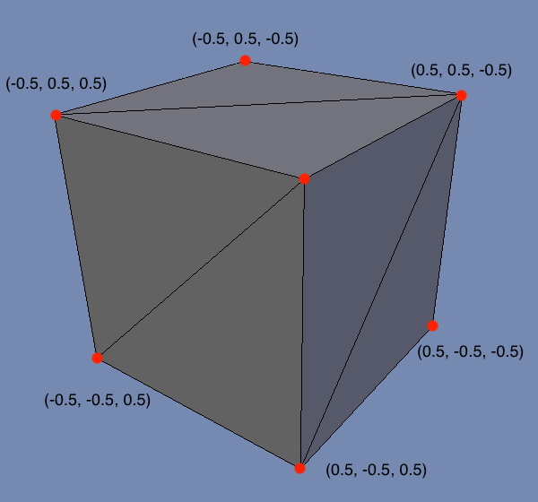
For example, here’s a visualization of a 3D cube object. It consists of 6 faces, where each face consists of two triangles. Each triangle is defined by three vertices (highlighted as red dots). Each vertex has a position in (X, Y, Z) coordinates.
It’s worth mentioning that 3D objects can be built in other ways (e.g. NURBS). You also occasionally see quads (4-sided polygons) being used instead of triangles (3-sided polygons). But for game development, the use of vertices and triangles is extremely common.
To render a simple 3D object on screen, we need to know two things:
- What is the “shape” of the object? This is defined by the positions of the vertices that make up the triangles of the object.
- How do we “fill in” the surface of the object? This is defined by a shader program, which we’ll discuss later in this post.
There are a couple other considerations (position of the object in the world, position of the camera/viewpoint in the world, etc), but we’ll touch on these in the future - no need to worry about them now!
The Plan
We will implement a 3D renderer in OpenGL. Long term, we’d like to support many graphics APIs (such as Direct3D), but for now, we’ll focus on just the one. OpenGL has pretty good cross-platform support. SDL also supports OpenGL out of the box, which is convenient.
We’ll also be making use of a library called GLEW. While not strictly required, GLEW provides access to some OpenGL functions that would otherwise be complicated to access. If we didn’t use GLEW, we’d have to write boilerplate code to access simple OpenGL functions. GLEW provides us with a header file that exposes such functions.
This post will walk through the initialization of an SDL application using OpenGL (including the integration of the GLEW library). We then want to render a simple triangle in 3D space, so we’ll discuss how to define the vertex data that defines the shape of the object. We’ll then explain how you can use a simple shader program to “fill in” the surface of the object with a solid color. And, finally, we’ll render the dang thing!
To summarize, we will need to perform the following steps to render a simple triangle:
- Integrate GLEW
- Initialize OpenGL and GLEW
- Define vertex data
- Load vertex data into OpenGL
- Write vertex and fragment shaders
- Load, compile, and link the vertex and fragment shaders
- Activate the shader program
- Send vertex data to be drawn
That’s actually quite a lot to cover! Let’s get to it.
Integrate GLEW
First, we need to get get our hands on the GLEW library. You can download GLEW as a pre-built library for Windows here. If you aren’t on Windows, you have two options:
- Download the source code and build from source, using the instructions on Github.
- Retrieve a pre-built library from a package manager. For example, on Mac, you can get the library with
Homebrew using
brew install glew.
Once we have the files, we put the library and include files in the Libraries folder:
Root/
  Libraries/
    GLEW/
        include/
            GL/
                glew.h
                glxew.h
                wglew.h
        lib/
            mac/
                libGLEW.dylib
            win/
Finally, modify the project to include GLEW in the compile and linking process:
- Add
Libraries/GLEW/includeto header search paths. - Add
Libraries/GLEW/libto library search paths. - Add
-lGLEWas a linker flag.
After this, the game should still compile and run without a problem.
Sidetrack: The Renderer Class
Our rendering code and data can become quite complicated, so it’s a good idea for us to introduce a new class, Renderer, rather than continue to pile this code into the GEngine class.
To start, our Renderer class looks something like this:
// Renderer.h
class Renderer
{
public:
    bool Initialize();
    void Shutdown();

    void Clear();
    void Render();
    void Present();

private:
    // Handle for the window.
    SDL_Window* mWindow = nullptr;

    // Context for rendering in OpenGL.
    SDL_GLContext mContext;
};
GEngine simply contains a renderer object:
// In GEngine.h
Renderer mRenderer;
As with GEngine, this class will need to be initialized and shutdown. We simply add calls to Renderer::Initialize() and Renderer::Shutdown() to the respective functions in GEngine.
Some of the logic that was previously in GEngine::Initialize() can also be moved to Renderer::Initialize(). For example, our calls to SDL_InitSubSystem and SDL_CreateWindow make more sense to be managed by the Renderer.
Ok, back on track - let’s look at how we initialize OpenGL!
Initializing OpenGL and GLEW
In our last post, we initialized the SDL video subsystem and created a basic SDL window. We still want to do this when using OpenGL, but we just need to augment those calls with a couple additional lines and some different arguments:
bool Renderer::Initialize()
{
    // Init video subsystem.
    if(SDL_InitSubSystem(SDL_INIT_VIDEO) != 0) { return false; }

    // Tell SDL we want to use OpenGL 3.3
    // These attributes must be set before creating the window.
    SDL_GL_SetAttribute(SDL_GL_CONTEXT_PROFILE_MASK, SDL_GL_CONTEXT_PROFILE_CORE);
    SDL_GL_SetAttribute(SDL_GL_CONTEXT_MAJOR_VERSION, 3);
    SDL_GL_SetAttribute(SDL_GL_CONTEXT_MINOR_VERSION, 3);

    // Use double buffering.
    SDL_GL_SetAttribute(SDL_GL_DOUBLEBUFFER, 1);

    // Require hardware acceleration.
    SDL_GL_SetAttribute(SDL_GL_ACCELERATED_VISUAL, 1);

    // We request from OpenGL at least 8-bits per channel for the color buffer.
    SDL_GL_SetAttribute(SDL_GL_RED_SIZE, 8);
    SDL_GL_SetAttribute(SDL_GL_GREEN_SIZE, 8);
    SDL_GL_SetAttribute(SDL_GL_BLUE_SIZE, 8);
    SDL_GL_SetAttribute(SDL_GL_ALPHA_SIZE, 8);

    // Create a window.
    mWindow = SDL_CreateWindow("GK3", 100, 100, 1024, 768, SDL_WINDOW_OPENGL);
    if(!mWindow) { return false; }

    // Create OpenGL context.
    mContext = SDL_GL_CreateContext(mWindow);
    if(mContext == NULL) { return false; }

    // Initialize GLEW.
    glewExperimental = GL_TRUE;
    if(glewInit() != GLEW_OK) { return false; }

    // Init succeeded!
    return true;
}
As we’ve done before, we first call SDL_InitSubSystem, and we don’t continue if it fails. The remaining code requires deeper explanation; let’s walk through it one step at a time.
OpenGL Attributes
Next, we must specify the OpenGL profile, major version, and minor version. OpenGL window creation will fail if these are not specified.
For a profile, we can choose Core, Compatibility, or ES. I don’t see any reason to use Compatibility (which enables deprecated functionality). ES, as in OpenGL ES, provides a subset of OpenGL functionality, which is primarily used on mobile devices. I chose to use Core, since we are primarily interested in desktop platforms at the moment.
The next question is what major/minor version to use? This is a trade-off between desired OpenGL features and hardware support. 3.3 was the last version released to target hardware that supports Direct3D 10+, whereas OpenGL 4 targets hardware that supports Direct3D 11+. 3.3 was released in 2010, so we’re at a point now where its hardware support is probably quite good. The game we’re targeting, GK3, is also not the most graphically advanced game, having been released in 1999. So, let’s just use OpenGL 3.3 for now!
I enabled double buffering, which we can use later in conjunction with VSYNC to avoid screen tearing. I also specify that I want to use hardware acceleration.
Finally, I request 8-bits per channel in the color buffer. I’m basically asking for 32-bit RGBA color.
Window and Context
After setting all these attributes, we can finally create our window. This is the same code we had in the previous post, with one important difference: the flag SDL_WINDOW_OPENGL is now passed as the last argument!
Once we have a valid window, we need to create an OpenGL context with SDL_GL_CreateContext. Without creating a context, rendering will not work, and your program will likely crash. An application can conceivably create multiple contexts, but there usually isn’t a compelling reason to do so. Certainly for this game engine, there is no need.
We need to save both the window and context as class member variables so that we can properly destroy them when the game is shutting down.
GLEW Init
There are a surprising number of OpenGL functions that we’ll need to use that aren’t available via default OpenGL header files. We will be using GLEW to access those functions with relative ease.
After integrating the library into our project, we need to initialize it. If we attempt to call various GLEW-provided function without initializing, we’ll likely crash our program.
Note that you must #include <GL/glew.h> to access GLEW and GL functions.
The glewExperimental variable is a bit mystifying/misleading. By setting this to true, we aren’t enabling some cutting edge or unstable part of GLEW. This is simply a flag that should ensure that GLEW properly loads the various required extensions, even if running on experimental or pre-release drivers. In practice, even basic functions sometimes fail without this turned on (at least on macOS) - so, we turn it on!
And with that, we’re pretty well initialized!
Defining Vertex Data
As mentioned earlier, a 3D object consists of a collection of vertices, and each vertex has a position in 3D space. A 3D position has three components (x, y, z). Games tend to represent these values using floating-point values (float).
For example, consider a very simple piece of 3D geometry we might want to render: a triangle. A triangle consists of three vertices.
To render a triangle, we will need to pass the vertex data to OpenGL, along with instructions for how to interpret those vertices. One common way to interpret the vertex data is “every three vertices is one triangle.” Since each vertex has three floating-point values, we could also phrase this as “every nine floating-point values is one triangle”.
As a result, we can define our simple triangle vertices in code like this, where every three floats represent one vertex position of our triangle:
float triangle_vertices[] = {
    0.0f,  0.5f,  0.0f,     // top
    0.5f, -0.5f,  0.0f,     // right
    -0.5f, -0.5f,  0.0f     // left
};
This is a triangle centered around the origin of a 3D coordinate system where +y is up and +x is right.
It’s uncommon to define vertex data directly in code like this, except for very simple debug shapes, such as this triangle. More frequently, you will read this vertex data from a file on disk, whether it is a common file format like FBX or OBJ, a simple text file where each line has one vertex on it, or GK3’s proprietary binary 3D mesh format!
Loading Vertex Data for OpenGL
Unfortunately, we can’t just pass our float array of vertex data directly to OpenGL.
OpenGL requires that you create a Vertex Buffer Object (VBO) and copy the vertex data into that buffer. We must also define a Vertex Array Object (VAO) that tells OpenGL how to interpret the data in the buffer.
We will encapsulate these operations in a new class called VertexArray. An instance of this class represents a piece of renderable 3D geometry for the underlying graphics library.
Here’s the header for this class:
// VertexArray.h
#pragma once
#include <GL/glew.h>

class VertexArray
{
public:
    VertexArray(const float* vertPositions, int vertPositionsCount);
    ~VertexArray();

    void Draw();

private:
    // Handles to VBO and VAO.
    GLuint mVBO = GL_NONE;
    GLuint mVAO = GL_NONE;

    int mVertexCount = 0;
};
Creating a Vertex Buffer Object
OpenGL can only render using data that is in video RAM (usually on the graphics card), whereas our float array exists in “regular” RAM. Creating a VBO and copying our vertex data into it effectively copies the vertex data to video RAM, where OpenGL is perfectly happy to use it for rendering.
Creating a VBO isn’t too tricky, though it isn’t exactly intuitive:
VertexArray::VertexArray(const float* vertPositions, int vertPositionsCount)
{
    // Each vertex position is 3 elements, so divide by 3 to get vertex count.
    mVertexCount = vertPositionsCount / 3;

    // Generate a buffer and bind it for use.
    glGenBuffers(1, &mVBO);
    glBindBuffer(GL_ARRAY_BUFFER, mVBO);

    // Allocate buffer of a certain size and copy vertex data into it.
    // Arguments are TARGET, SIZE, DATA, USAGE
    glBufferData(GL_ARRAY_BUFFER, vertPositionsCount * sizeof(float), triangle_vertices, GL_STATIC_DRAW);
}
The variable mVBO is a “handle” to a buffer object. It isn’t the buffer itself, and it isn’t a pointer to the buffer - it is simply an unsigned integer that identifies the buffer in the graphics system. When we call glGenBuffers, we are only allocating a small, lightweight handle.
We then need to bind the buffer using glBindBuffer. Many commands in OpenGL operate on whatever happens to be the bound buffer. Therefore, it’s important to bind the desired buffer before calling certain commands.
Our call to glBufferData does the heavy-lifting of allocated a buffer of the appropriate size, copying our vertex data into it, and associating it with the bound VBO handle. For the size (in bytes), we use vertPositionsCount * sizeof(float) because our triangle is 9 floats, and each float is 4 bytes. Floats are almost universally 4 bytes, but it is best to use sizeof so we don’t have to assume!
The final “usage” argument we don’t need to worry about at this time. The two options are GL_STATIC_DRAW and GL_DYNAMIC_DRAW. The purpose is to provide a hint to the graphics system about how frequently the contents of the VBO will change. “Static” indicates that it won’t change at all, while “Dynamic” means it may change frequently. If we planned to update our buffer frequently (perhaps if we were animating vertex data), we may choose to mark the buffer as “dynamic,” which could improve performance. For our simply triangle, “static” will do just fine.
Creating a Vertex Array Object
If we can use a VBO to load our vertex data into video memory for OpenGL, then why in the world do we need another object called a VAO? While a VBO provides the vertex data, we haven’t yet specified HOW to interpret that data.
OpenGL needs to know a few things about the vertex data we are providing:
- How many vertex attributes are we providing? For our simple example, we are providing just the vertex positions, but it is also possible to provide other attributes like vertex colors, vertex normals, texture mapping coordinates, etc.
- What byte offsets within the VBO does each vertex attribute’s data reside at?
- How many components exist for each vertex for this attribute? For position data, this is usually 3 (for X, Y, and Z), but for something like color, it could be 4 (for red, green, blue, and alpha values).
- What is the type of the data? We often specify positions as floats, but we have the option to use different data types like bytes, shorts, and ints.
- Is the vertex data tightly packed in the VBO, or are different types of data interleaved? We might provide all vertex positions at once, and then all vertex colors at once. Or, we might provide all the data for a single vertex at once, followed by the next, etc.
This might seem like a lot of options to process - here are a few different examples of how data could be laid out in a VBO:
- Vertex positions consist of 3
floatvalues that are tightly packed into memory one after the other starting at byte offset 0. - Vertex positions consist of 3
floatvalues that are tightly packed into memory one after the other starting at byte offset 0. Vertex colors consist of 4bytevalues that are tightly packed into memory one after the other starting at byte offset 36. - Vertex positions consist of 3
floatvalues starting at byte offset 0, with each position having an offset of 4 bytes between. Vertex colors consist of 4bytevalues starting at byte offset 12 with each color having an offset of 12 bytes between.
To help visualize the idea of interleaving data, consider an example where we have vertex data for a triangle, with each vertex having position and color attributes. There are two ways we could lay out this data in our VBO:
// Option 1 (packed data)
[V1Pos][V2Pos][V3Pos][V1Color][V2Color][V3Color]

// Option 2 (interleaved data)
[V1Pos][V1Color][V2Pos][V2Color][V3Pos][V3Color]
The key point is this: OpenGL doesn’t make assumptions about the layout of the data in the VBO. There are many different ways to layout the data in the VBO, and there are different scenarios where one way could make more sense than another. So, we use a VAO to tell OpenGL how we have the data laid out.
For our simple triangle example, we can create our VAO like so:
VertexArray::VertexArray(const GLfloat* vertPositions, int vertPositionsCount)
{
    // VBO creation code omitted...

    // Generate and bind our VAO.
    glGenVertexArrays(1, &mVAO);
    glBindVertexArray(mVAO);

    // Enable vertex attribute 0 (vertex position data).
    glEnableVertexAttribArray(0);

    // Make sure VBO is bound, so the VAO knows what buffer to use in conjunction with the VAO.
    glBindBuffer(GL_ARRAY_BUFFER, mVBO);

    // Vertex attribute 0 (position data) has 3 components per vertex (x, y, z) and each is a float.
    // We don't want this data normalized (GL_FALSE), and the data is tightly packed (0).
    // There is no byte offset required (NULL).
    glVertexAttribPointer(0, 3, GL_FLOAT, GL_FALSE, 0, NULL);
}
As with our VBO, we allocate a small, lightweight handle object mVAO using the glGenVertexArrays function. We immediately bind the VAO using glBindVertexArray, since we’re about to run VAO commands with our VAO as the target.
For rendering, we can enable several possible vertex attributes: position, color, UV texture mapping coordinates, normals, tangents, etc. By default, all our disabled. We use glEnableVertexAttribArray to enable at least index 0, which we’ll use for our vertex position data. There’s a not so large limit on the number of attributes - it’s sometimes 8 or 16 or less!
If we haven’t done so already, we need to bind our VBO using glBindBuffer. When we want to render our triangle, we will do so using the VAO. If we bind our VBO before calling glVertexAttribPointer, the VAO remembers what VBO it should use later on for rendering. In short, if we don’t do this, the VAO doesn’t keep track of what VBO to use, and we get no output to the screen!
Finally, we call glVertexAttribPointer. This is a beefy function! There’s a lot of potential to accidentally provide the wrong data. So, let’s break down what’s going on here.
We call glVertexAttribPointer one time per attribute that we have enabled with glEnableVertexAttribArray. In this case, we only enabled one attribute, for vertex position, so we only need to call glVertexAttribPointer once, to provide the details for how the position data is laid out in the VBO. This is the first argument provided (0), which is the attribute index we are specifying data for.
The next two values are fairly simple: how many numbers per vertex, and what type are the numbers? Our vertex positions are defined as points in 3D space (x, y, z), and each one is a float. As such, we pass 3 and GL_FLOAT.
The next argument specifies whether we want the data to be normalized or not. For some data, like colors, this might make sense. For position data, this is not at all a good idea, so we say GL_FALSE.
The next argument is called “stride”, and it indicates whether our attribute data is tightly packed or interleaved amongst other data. A value of 0 indicates tight packing, whereas any other value indicates that there are 1, 2, 3, 4, etc bytes of other data between each vertex’s attribute data. As described above, this can happen based on how you define your vertex data. We use 0 because we only have one attribute, so it’s “packed” by default.
Finally, we have an offset into the VBO at which we can find the first instance of this attribute. Since we have only one attribute, the first instance is at offset 0, so we pass NULL (0 would also work). If we had another attribute, like color, we would definitely need to provide an offset here.
At long last, we have a VBO and VAO defined, which we can use for rendering!
Rendering the VAO
To render a VAO, we define a function called Draw:
void VertexArray::Draw()
{
    glBindVertexArray(mVAO);
    glDrawArrays(GL_TRIANGLES, 0, mVertexCount);
}
We bind the VAO we want to render using glBindVertexArray. Finally, we issue the draw command glDrawArrays.
glDrawArrays allows us to specify an offset into the vertex data to start rendering at, plus a count for the number of vertices to render. In our case, we want to start rendering at index 0, and we want to render all vertices (all 3 of them).
The first argument, GL_TRIANGLES, tells OpenGL how to render the vertex data. There are several options - here are a few examples:
GL_TRIANGLES: Interpret every 3 vertices as a single triangle.GL_TRIANGLE_STRIP: Interpret the first 3 vertices as a single triangle. After that, each new vertex creates a triangle with the previous 2 vertices.GL_TRIANGLE_FAN: The first vertex is shared between all triangles. Every vertex after the second vertex defines a triangle with the previous vertex and the first vertex.GL_LINES: Interpret every 2 vertices as a line.
We’ll often use GL_TRIANGLES, but we may have a need to use various other options as we implement different types of rendering.
Before we move on, don’t forget the destructor for VertexArray, which deletes the objects we created in the constructor:
VertexArray::~VertexArray()
{
    if(mVBO != GL_NONE)
    {
        glDeleteBuffers(1, &mVBO);
    }
    if(mVAO != GL_NONE)
    {
        glDeleteVertexArrays(1, &mVAO);
    }
}
Writing a Shader
After ALL that work to create our VBO and VAO, if we tried to render, we’d get…nothing!
Though we have defined our vertex data and how to interpret it, we have not yet defined how to “fill in” the surfaces of the shape when it is drawn. For example, do we want to fill in the surface of the shape with a color? If so, what color? Or maybe we want to display a texture on the surface? We haven’t specified that yet, and so nothing is rendered.
In modern graphics libraries, such decisions are usually expressed in a shader program. A simple shader program consists of two parts, a vertex shader and a fragment shader. The vertex shader executes first and is responsible for performing any operations on the individual vertices of the object being rendered. The fragment shader runs second and is responsible for performing operations on the individual output pixels in the color buffer.
The most critical function of a shader is this: for ever pixel on screen that will be used to render a 3D object, decide on a color value to use. It’s that simple. That being said, properly deciding on a color value based on desired visual effects, lighting, and other considerations is another challenge entirely!
Both the vertex and fragment portions of a shader are written in a special programming language called a shader language. Unfortunately, there is not one single shader language - OpenGL uses a shader language called glsl, Direct3D uses another shader language called hlsl, and many other shader languages also exist. Many shader languages have similar syntaxes though, which is nice.
You write vertex and fragment shaders as text files containing the shader code for each part. At runtime, you load the text files, compile them, and link them into a final shader program. Compiling and linking of shaders at runtime can fail for a variety of reasons - a typo, a syntax error, unsupported features, etc. It’s also possible to “pre-compile” shader programs and save them in a binary format (for performance reasons), but we won’t worry about that for now.
For our simple triangle rendering needs, we can define two very simple files for our vertex and fragment shaders:
// Simple.vert
#version 330

in vec3 position;

void main(void) {
    gl_Position = vec4(position, 1.0);
}
// Simple.frag
#version 330

out vec4 outColor;

void main(void) {
    outColor = vec4(0.5, 0.0, 0.5, 1.0);
}
Create two files called Simple.vert and Simple.frag with the above contents in each. Let’s quickly review what these two files are doing.
Vertex Shader Explained
Remember, the vertex program runs first for every vertex of the object we want to render. For our simple triangle, this will run for all three vertices of the triangle. We could conceivably do much more in the vertex shader, and in the future, we will use the vertex shader to perform transformations that enable mesh instancing and a moveable 3D camera. For the time being, however, we keep it simple.
The version number line indicates to OpenGL what version of the glsl shader language we want to use. 330 is the version that came with OpenGL 3.3. You might choose one version or another because newer versions support additional features! Since we chose OpenGL 3.3 earlier, we’ll use the version 330 compiler.
The in vec3 position; line defines what vertex attribute data we are expecting to get for each vertex. As described earlier in this post, we are only passing position data for each vertex. If we were passing other data, like color, we’d have additional in lines specified here. There is a correlation between the lines here and the calls to glEnableVertexAttribArray we performed when creating the VAO.
Finally, we have our “main” function - this may look somewhat familiar from a C or C++ program! We are currently not doing anything special to our vertex position - we just pass it through as-is without modifying it.
During the vertex shader function, we must assign the special OpenGL variable gl_Position with our desired position, in 3D space, for the vertex. For the time being, we just want to use the exact same position we passed in. Since our “in” position is of type vec3, and gl_Position is a vec4, we must cast from vec3 to vec4. We’ll talk about “vectors” in a later blog post, but just know that a vec3 has 3 elements (x, y, z) and a vec4 has 4 elements (x, y, z, w). Both can be used to represent a position in 3D space.
Fragment Shader Explained
The fragment shader is not much different in structure from the vertex shader. But it’s purpose is quite different - while our vertex shader runs once per vertex of the rendered object (3 times for our triangle), the fragment shader will run one time per output pixel for the rendered object. How many pixels does our triangle have? Well…it depends on the screen resolution and the object’s position on screen! So, it is more difficult to quantify how many times the fragment shader will execute, but it almost certainly runs more times than our vertex shader.
The purpose of a fragment shader is also different. The fragment shader should decide on a final output color for each pixel of the rendered object.
In our case, we define an out vec4 outColor; variable - we just need to assign our final color to this variable by the end of the fragment shader “main” function. Our actual fragment shader function is quite simple too: we just set outColor to some color (purple), and that’s it.
Loading a Shader
As mentioned earlier, writing the shaders is only part of the battle - we also need to load the shaders at runtime to use them for rendering! The process for this is fairly simple: we use the file I/O mechanisms of C++ to read in the contents of the files Simple.vert and Simple.frag. We pass the contents of each file to OpenGL to be compiled. If that succeeds, we then “link” the compiled vertex and fragment shaders to create a single “shader program” object.
The code for this isn’t too tricky, but it’s important to handle errors and log compiler errors to assist in debugging. I’ll encapsulate the concept of a shader in a class called Shader.
// Shader.h
#pragma once
#include <GL/glew.h>

class Shader
{
public:
    Shader(const char* vertShaderPath, const char* fragShaderPath);
    ~Shader();

    bool IsGood();
    void Activate();

private:
    // Handle to the compiled and linked GL shader program.
    GLuint mProgram = GL_NONE;

    // Did we encounter an error during compile/linking?
    bool mError = false;

    GLuint LoadAndCompileShaderFromFile(const char* filePath, GLuint shaderType);
    bool IsShaderCompiled(GLuint shader);
    bool IsProgramLinked(GLuint program);
};
Since reading in and compiling a shader is the same for both the vertex shader and fragment shader, we create a function that can do this for either:
GLuint Shader::LoadAndCompileShaderFromFile(const char* filePath, GLuint shaderType)
{
    // Open the file, but freak out if not valid.
    std::ifstream file(filePath);
    if(!file.good())
    {
        std::cout << "Couldn't open shader file for loading: " << filePath << std::endl;
        return GL_NONE;
    }

    // Read the file contents into a char buffer.
    std::stringstream buffer;
    buffer << file.rdbuf();
    std::string fileContentsStr = buffer.str();
    const char* fileContents = fileContentsStr.c_str();

    // Create shader, load file contents into it, and compile it.
    GLuint shader = glCreateShader(shaderType);
    glShaderSource(shader, 1, &fileContents, nullptr);
    glCompileShader(shader);
    return shader;
}
The filePath used must be relative to the working directory for the program, which will usually be the same directory the executable is in. When I build and run in Xcode, the working directory for the executable is some random build directory. So, for the above to work, we need to copy our shaders into the same folder as our executable, or tell Xcode/Visual Studio that our working directory should be something else!
After reading in the file contents as a const char*, we can create a shader handle (glCreateShader). The “shaderType” is either GL_VERTEX_SHADER or GL_FRAGMENT_SHADER.
The function glShaderSource copies the shader text into OpenGL, associating it with the given handle. The additional arguments allow for scenarios where you might pass in a shader one line at a time or something like that, but we’ve just got the shader as one big string that is null terminated. So, we can simply say “we’ve got 1 string, here it is, no length value needed”.
Finally, we call glCompileShader, which does the compiling. It may succeed, or it may fail. To find out, we need another function:
bool Shader::IsShaderCompiled(GLuint shader)
{
    // Ask GL whether compile succeeded for this shader.
    GLint compileSucceeded = 0;
    glGetShaderiv(shader, GL_COMPILE_STATUS, &compileSucceeded);

    // If not, we'll output the error log and fail.
    if(compileSucceeded == GL_FALSE)
    {
        GLint errorLength = 0;
        glGetShaderiv(shader, GL_INFO_LOG_LENGTH, &errorLength);

        GLchar* errorLog = new GLchar[errorLength];
        glGetShaderInfoLog(shader, errorLength, &errorLength, errorLog);

        std::cout << "Error compiling shader: " << errorLog << std::endl;
        delete[] errorLog;
        return false;
    }

    // GL reports the compilation was successful!
    return true;
}
We can pass any shader handle from OpenGL to this function, and it’ll return true or false for whether compilation succeeded. It’ll even output any compiler errors if compilation failed.
Our Shader constructor uses these functions to load and compile the shader, given a file name:
Shader::Shader(const char* vertShaderPath, const char* fragShaderPath)
{
    // Compile default shader program.
    GLuint vertexShader = LoadAndCompileShaderFromFile(vertShaderPath, GL_VERTEX_SHADER);
    GLuint fragmentShader = LoadAndCompileShaderFromFile(fragShaderPath, GL_FRAGMENT_SHADER);
    if(!IsShaderCompiled(vertexShader) || !IsShaderCompiled(fragmentShader))
    {
        glDeleteShader(vertexShader);
        glDeleteShader(fragmentShader);
        mError = true;
        return;
    }

    // Assemble shader program.
    mProgram = glCreateProgram();
    glAttachShader(mProgram, vertexShader);
    glAttachShader(mProgram, fragmentShader);

    // Link the program.
    glLinkProgram(mProgram);

    // If linking failed, clean up and return error.
    if(!IsProgramLinked(mProgram))
    {
        glDeleteProgram(mProgram);
        glDeleteShader(vertexShader);
        glDeleteShader(fragmentShader);
        mError = true;
        return;
    }

    // Detach shaders after a successful link.
    glDetachShader(mProgram, vertexShader);
    glDetachShader(mProgram, fragmentShader);
}
First, we use our functions LoadAndCompileShaderFromFile and IsShaderCompiled to compile our vertex and fragment shaders. Then, we create a “shader program” handle with glCreateProgram - per usual with OpenGL, this is just a lightweight handle to a program. We then attach our two shaders to the program using glAttachShader.
We then “link” the program using glLinkProgram. If the link step succeeds, we can finally use our shader for rendering! After a successful link, we should detach the previously attached shaders with glDetachShader. If linking fails, we just clean up and return an error.
The function IsProgramLinked is one that I defined:
bool Shader::IsProgramLinked(GLuint program)
{
    // Ask GL whether link succeeded for this program.
    GLint linkSucceeded = 0;
    glGetProgramiv(program, GL_LINK_STATUS, &linkSucceeded);

    // If not, we'll output the error log and fail.
    if(linkSucceeded == GL_FALSE)
    {
        GLint errorLength = 0;
        glGetProgramiv(program, GL_INFO_LOG_LENGTH, &errorLength);

        GLchar* errorLog = new GLchar[errorLength];
        glGetProgramInfoLog(program, errorLength, &errorLength, errorLog);

        std::cout << "Error linking shader program: " << errorLog << std::endl;
        delete[] errorLog;
        return false;
    }

    // GL reports the linking was successful!
    return true;
}
This function is similar to our IsShaderCompiled function - it checks with OpenGL that the program has linked successfully, and if not, it outputs an error log.
There are a couple more functions defined for Shader:
Shader::~Shader()
{
    if(mProgram != GL_NONE)
    {
        glDeleteProgram(mProgram);
    }
}

bool Shader::IsGood()
{
    return !mError;
}

void Shader::Activate()
{
    glUseProgram(mProgram);
}
The destructor is needed so that we properly delete the program created in the constructor. IsGood simply returns whether we encountered any error with the shader loading/compiling/linking. Finally Activate must be called before rendering an object, so that this shader will be used when rendering - this just calls glUseProgram, which “activates” the shader program in OpenGL.
Bringing It All Together
We are finally ready to render our triangle. We add to our Renderer::Initialize() function to create our VertexArray and Shader objects:
bool Renderer::Initialize()
{
    // SDL, GL, and GLEW init omitted...

    // Load shader.
    mShader = new Shader("Simple.vert", "Simple.frag");
    if(!mShader->IsGood()) { return false; }

    // Create vertex array from triangle vertices.
    mTriangle = new VertexArray(triangle_vertices, 9);

    // Init succeeded!
    return true;
}
In GEngine::GenerateOutputs, we add this:
void GEngine::GenerateOutputs()
{
    mRenderer.Clear();
    mRenderer.Render();
    mRenderer.Present();
}
And at this point, our Clear, Render, and Present functions are quite simple:
void Renderer::Clear()
{
    glClear(GL_COLOR_BUFFER_BIT | GL_DEPTH_BUFFER_BIT);
}

void Renderer::Render()
{
    mShader->Activate();
    mTriangle->Draw();
}

void Renderer::Present()
{
    SDL_GL_SwapWindow(mWindow);
}
Every time we render, we must first clear the buffer using glClear. It’s most critical that we clear the color buffer at this point.
Next, we actually render our various 3D objects to the now cleared buffer. For our triangle, we activate the shader (which calls glUseProgram) and then draw our triangle (which calls glDrawArrays).
Finally, since we are using double buffering, all this rendering thus far has occurred on the back buffer. In order for the user to see anything we rendered, we need to “swap” the back and front buffers. Our back buffer then becomes the front buffer, and next frame, we’ll draw to our new back buffer, which was previously the front buffer. The act of swapping the front and back buffers is sometimes called “swap”, sometimes called “present”. The SDL command is SDL_GL_SwapWindow.
After all that, you should see on-screen something like this:

Finally!
You can modify the color used in the fragment shader. If you’re having trouble loading your shaders, make sure they are located in the right folder, wherever the program executable is.
Conclusion
This post introduced three foundational rendering classes that’ll be augmented and used extensively as we move forward: Renderer, VertexArray, and Shader. Despite the large amount of groundwork required to even get a simple triangle rendering on-screen, the majority of what has been written can now be used to render any 3D object with relative ease.
If you run into issues, check out the commit in the G-Engine repo that contains this code. Note that I’ve renamed and finessed a few things in this blog post for ease of reading and clarity, so the committed code is not exactly the same.
Now that we can render a 3D object, our next goal will be the ability to move the 3D object to a desired position in 3D space, plus the ability to move our camera. But before we do that, we’ll need to implement some math classes for Vectors and Matrices - stay tuned!